Heat Transfer Fundamentals for Semiconductor Devices

Where semiconductor devices are getting smaller, faster & operating at higher power, it is inevitable that heat will be generated. When the heat goes beyond a certain threshold, the performance & efficiency of the IC device will drop significantly. Efficient heat transfer is a critical aspect that must be considered in the design of the thermal solution. There are 3 key areas to consider in understanding the best match & mix in the design:

  1. IC device
    • What is the maximum device power?
    • Actual heat generation from the IC device. 
      • Let me give a simple illustration, even if the maximum power of the device may be 200W, however, this will not be a constant, and will change depending on the actual utilization level. Using high level gaming or AI simulation may take up more power resources which will increase the temperature, but using standard Excel, Words, etc will take up very low power resources.
  2. Cooling system
    • A cooling system can be a traditional heat sink, heat pipe, water or refrigerant chiller.  
    • Selection of the cooling system will depend on the desired temperature to achieve, cooling down rate & space available for installation. It is important to have a cooling volume to handle the removal of the heat 
  3. Thermal interface material (TIM)
    • There are many types of TIM available, including thermal paste, thermal pad, graphite foil, phase change material or liquid metal.
    • The selection will be dependent on costs, surface warpage, applied pressure, expected performance, etc 

The heat transfer for a semiconductor device can be viewed in 3 different parts:

  1. Heat transfer within the IC package
    • The heat transfer mechanism & TIM stack-up for lidless & lidded device will be slightly different. Please see below for the explanation.
  2. Heat transfer from the IC package to the cooling medium
    • There are different options of cooling medium
      • Direct to product casing/chassis
      • Heatsink/Fan
      • Heat-pipe/Fan
      • Liquid Cooling
      • Refrigerant Cooling
    • The selection of TIMs will depend on the operating condition & mechanical constraint for the installation  
  1. Heat transfer from the cooling medium to the environment
    • The environment temperature will affect the outcome of the heat transfer efficiency.

In the semiconductor device, there are 2 categories of IC packages, ie lidded & lidless. Both configurations will have different stack-ups of the TIM in the final field installation & production testing. 

Lidless Package

For a lidless package, the die will be mounted directly onto the device package via flip-chip process. Due to space limitation, the package will normally be surface mounted directly to the PCB board as it will be used for laptop or mobile devices. When installed, the die will be dissipated directly to the cooling medium. As for the lidded package, there will be a metal cover over the die on the package. In this case, there is a need to have a TIM between the top of the die & the metal cover to ensure that the heat will be transferred out.

In the heat transfer for the lidless package, care has to be exercised when installing the TIM as the die is brittle and can be damaged until direct impact force or high-pressure compression. Another possible issue will be shorting of the passive components by the TIM. As the die is small, the cooling capacity of the cooler should be sized upward since the heat is dissipated through a small surface area. One of the options to consider is the use of pyrolytic graphite, which is synthetically made with highly oriented graphite polymer film & has high in-plane thermal conductivity (can be more than 1900W/m-K).

If this is for laptop or mobile devices, the heat will be transferred from the device to the casing to dissipate the heat evenly.

Lidded Package

For a lidded package, the die will be mounted directly onto the device package via flip-chip process, after which there will be a metal lid to be sealed on the PCB substrate to cover & protect the die. The package will normally be mounted onto a socket on the PCB board. Such packages are commonly used for desktop & server products. 

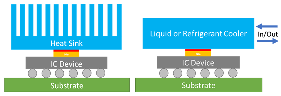
In this setup, there is a need to have a TIM between the die & the metal lid to ensure that the heat from the die will be transferred out efficiently. There will also be a TIM between the top of the metal lid to the cooling medium. 

The cooling medium can be in the form of heatsink/fan, heat-pipe/fan, liquid cooling or refrigerated cooling. It is common for gamers to use liquid cooling for the CPU to improve the speed & performance during their gaming.

For production testing in the factory, all CPU/GPU will undergo 100% system level testing to simulate the real-environment software utilization at elevated temperature. The configuration for the cooler/heater will have additional features & capability to control the temperature accurately & with high response sensitivity to the temperature & power change. 

The choice on the selection of the thermal solution will be dependent on the expected performance for the IC device, available space & budget.